| Brand Name: | Sinuo |
| Model Number: | SNQC1008 |
| MOQ: | 1 |
| Price: | Customized |
| Payment Terms: | T/T |
| Supply Ability: | 10 sets per month |
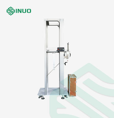
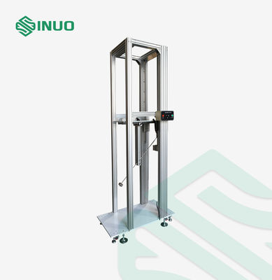
High Energy Pendulum Hammer Impact Tester for EV Chargers IEC 61851-1 IK Code Testing
The SNQC1008 High Energy Pendulum Hammer Impact Tester is designed for mechanical strength and impact resistance testing of EV charging stations, electrical enclosures, power distribution cabinets, metering boxes, and switchgear cabinets.
Complying with IEC 60068-2-75, IEC 62262 IK impact protection requirements, and IEC 61851-1 Clause 12.11, the tester evaluates the ability of equipment housings to withstand external mechanical impacts through controlled pendulum and vertical hammer impact tests.
The SNQC1008 is widely used by EV charger manufacturers, electrical equipment manufacturers, testing laboratories, and R&D centers for IK impact verification and enclosure durability assessment.
| Application Area | Typical Test Samples |
|---|---|
| EV Charging Equipment Testing | AC charging stations, DC charging stations, EVSE housings |
| Electrical Enclosure Impact Testing | Metering boxes, distribution cabinets, switchgear cabinets |
| Industrial Electrical Safety Testing | Power electronic equipment and outdoor electrical enclosures |
| Certification Laboratory Testing | IK protection level verification according to IEC standards |
| Specimen and Limitations | Electric vehicle charging stations; Power distribution cabinets; Metering boxes; Switchgear cabinets |
| Test Principle |
Test Eha(Pendulum Hammer Test): The impact element is released freely from a specified height through a 1-meter pendulum tube and strikes the specimen at the lowest point of the pendulum path. The impact energy is generated by the conversion of gravitational potential energy into kinetic energy, thereby achieving the purpose of impact testing on the specimen. Test Ehc (Vertical Hammer Test): The impact element is released freely from a specified height through a guide tube and strikes the specimen at the lowest point of the vertical travel. The impact energy is generated through the conversion of gravitational potential energy into kinetic energy, thereby achieving the purpose of impact testing on the specimen. |
| Structure and Features | Trolley structure with vertically adjustable mounting bracket and impact angle, suitable for different sizes of EV charging stations and impact height requirements. |
| Operating Environment | Overall dimensions:W1300*D600*H3200mm;Weight: Approx.250kg |
| Model | SNQC1008 | SNQC1008A | SNQC1008B | |
| Control & Operation | Button operation | PLC control, touchscreen operation | PLC control, touchscreen operation | |
| Sample Platform | No | Yes | Yes | |
| Secondary Impact Prevention Function | Yes | Yes | Yes | |
| Test Specimen Range |
Note: The maximum size of charging stations installed on the sample platform shall not exceed W×D×H = 1 × 1 × 2.0 m. The height of floor-standing charging stations shall not exceed 2.0 m.
|
|||
| Test Items |
|
|||
| Drive System |
Lifting: Motor + reducer drive Release mechanism: Electromagnetic release |
|||
| Transmission System | Precision ball screw + linear guide rail | |||
| Impact Energy |
Pendulum Hammer:2 J, 5 J, 10 J, 20 J, 50 J Vertical Hammer: 2 J, 5 J, 10 J, 20 J, 50 J (optional) |
|||
| Equivalent Mass of Impact Elements |
Pendulum Hammer: 500g,1.7kg,5kg,5kg,10kg±2%,(Angular impact head optional) Vertical Hammer: 500g,1.7kg,5kg,5kg,10kg±2% (optional) Stainless steel construction |
|||
| Pendulum Tube |
Length:1000㎜,Outer diameter: 15.9 mm steel tube Length:1000㎜,Outer diameter: 10.0 mm steel tube |
|||
| Vertical Hammer Sleeve | Guide sleeve matched with different hammer heads, stainless steel tube | |||
| Impact Position Height of Specimen (Pendulum Lifting Height) | Electrically adjustable up and down,Stroke: 300–1800 mm | |||
| Vertical Hammer Impact Height | 500-2000mm | |||
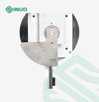
| Drop Height(Pendulum Impact Height) | 0–500 mm, with scale indication corresponding to the pendulum rotation angle; the pendulum can rotate from 0° to 90° | |||
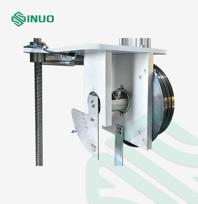
| Fixing and Release of Impact Element | Pin-type electromagnetic fixing and release mechanism | |||
| Base Plate | Thickened load-bearing steel base plate | |||
| Moving Method | Equipped with support feet and casters, allowing movement to the required impact position. | |||
| Optional Function | Secondary impact prevention function | |||
| Appendix | Reference Table for Selection of Impact Energy and Impact Elements | |||
Appendix Tables: Table 1 Characteristics of Impact Elements
| Energy/J | ≤1 ±10% | 2 ±5% | 5 ±5% | 10 ±5% | 20 ±5% | 50 ±5% |
| Equivalent Mass ±2%kg | 0.25(0.2) | 0.5 | 1.7 | 5 | 5 | 10 |
| Material | Nylon | Steel | ||||
| R/mm | 10 | 25 | 25 | 50 | 50 | 50 |
| D/mm | 18.5(20) | 35 | 60 | 80 | 100 | 125 |
| f/mm | 6.2(10) | 7 | 10 | 20 | 20 | 25 |
| r/mm | - | - | 6 | - | 10 | 17 |
| l/mm | Determined according to the equivalent mass, see Appendix A | |||||
Table 2 Drop Height
| Energy/J | 0.14 | 0.2 | (0.3) | 0.35 | (0.4) | 0.5 | 0.7 | 1 | 2 | 5 | 10 | 20 | 50 | ||
| Equivalent Mass/kg | 0.25 | (0.2) | 0.25 | (0.2) | 0.25 | (0.2) | (0.2) | 0.25 | 0.25 | 0.25 | 0.5 | 1.7 | 5 | 5 | 10 |
| Drop Height ±1%mm | 56 | (100) | 80 | (150) | 140 | (200) | (250) | 200 | 280 | 400 | 400 | 300 | 200 | 400 | 500 |
|
Note 1: See Note in Clause 3.2.2. Note 2:The energy unit Joule (J) in this part is derived from the standard gravitational acceleration (g), where the rounded value of g is taken as 10 m/s². |
|||||||||||||||
Table 3 Relationship Between IK Code and Corresponding Impact Energy
| IK Code | IK00 | IK01 | IK02 | IK03 | IK04 | IK05 | IK06 | IK07 | IK08 | IK09 | IK10 | IK11 |
| Impact Energy/J | a | 0.14 | 0.2 | 0.35 | 0.5 | 0.7 | 1 | 2 | 5 | 10 | 20 | 50 |
| Note:IK11 is intended for special enclosures or protective grids used in extremely harsh outdoor environments. When specified in the relevant product standards, IK11 shall not replace the sandbag test. | ||||||||||||
| a According to this standard, no protection is provided. | ||||||||||||